
 Name: FSL-type axial compensators double rod
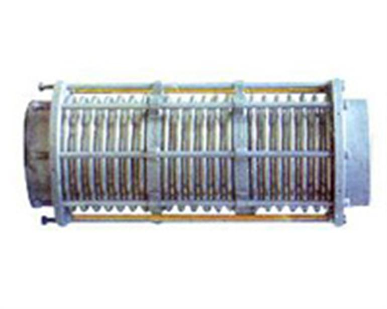
factory production of axial-type double-rod compensator, is a successful experience of similar products at home and abroad, a painstaking process developed advanced, easy to install the plumbing. Among medium and large caliber double rod axial compensator is one of the company's leading products, especially in the design and production of axial-type double-rod compensation devices, has been at the absolute leader in the domestic level.
Uses: FSL-type axial-type double-rod bellows simple structure, large amount of compensation, generally used in low frequency fatigue, require a large amount of the compensation line.
Model: DN32-DN3000, level 0.1Mpa-2.5Mpa Pressure
connection: 1, flange 2, to take over connected
products Axial compensation: 72mm-500mm
A model example:
For example: 0.6FSL200 × 12J
, said: Working pressure 0.6MPa, diameter DN = 200mm, wave number 12, took over the connection of the double-rod bellows.
Second, the application notes:
1, double rod bellows, simple structure, large amount of compensation, generally used in low frequency fatigue, require a large amount of the compensation line.
2, the samples are given compensation under the 1000 number of fatigue axial compensation.
3, flange standard JB81-59 by machine supplier, according to user requirements according to national standard, standard or other standards of delivery.
Third, the fixed bearing force:
pressure-driven: Fp = 100 · P · A (N)
Axial stretch: Fx = f · Kx · X (N)
where: P: maximum working pressure or the maximum test pressure MPa ;
A: effective area (check samples) square meters;
Kx: compensator axial stiffness N / mm;
X: the use of axial compensator compensation mm
f: factor, when the compensator pre-deformation, f is 1 / 2, when the compensation does not pre-deformation, f of 1.
FSL double rod-type axial compensators data
|
Nominal diameter (mm)
|
Model
|
Compensation
|
Stiffness (N / mm)
|
Effective area
(cm 2) |
Radial maximum size
(mm) |
Take over the port size
(Φ × δ) |
Case diameter
(mm) |
Length (L) (mm)
|
|||||||
|
Axial Xo
|
Horizontal Yo
|
Angular θo / degrees
|
Axial Kx
|
Horizontal Ky
|
Angular KQN-m / degree
|
Flange
|
Over
|
||||||||
|
32
|
QM
|
BW1.0/32 × 8
|
J
|
7
|
441
|
16
|
|
Φ38 × 3.5
|
186
|
|
280
|
||||
|
JZ
|
F
|
7
|
1.28
|
± 4
|
441
|
774
|
2
|
225
|
|
164
|
|
||||
|
QM
|
BW1.0/32 × 16
|
J
|
14
|
220
|
16
|
|
186
|
|
321
|
||||||
|
JZ
|
F
|
14
|
5.1
|
± 8
|
221
|
97
|
1
|
225
|
|
216
|
|
||||
|
40
|
QM
|
BW1.0/40 × 8
|
J
|
10
|
318
|
23
|
|
Φ45 × 3.5
|
224
|
|
289
|
||||
|
JZ
|
F
|
10
|
1.5
|
± 4
|
318
|
696
|
2
|
244
|
|
219
|
|
||||
|
QM
|
BW1.0/40 × 16
|
J
|
19
|
158
|
23
|
|
224
|
|
334
|
||||||
|
JZ
|
F
|
19
|
6.1
|
± 8
|
158
|
87
|
1
|
244
|
|
219
|
|
||||
|
50
|
QM
|
BW1.0/50 × 8
|
J
|
12
|
635
|
37
|
|
Φ57 × 3.5
|
239
|
|
306
|
||||
|
JZ
|
F
|
12
|
2.2
|
± 4
|
635
|
1041
|
6.4
|
259
|
|
182
|
|
||||
|
QM
|
BW1.0/50 × 16
|
J
|
24
|
318
|
37
|
|
239
|
|
372
|
||||||
|
JZ
|
F
|
24
|
8.9
|
± 8
|
318
|
130
|
3.2
|
259
|
|
247
|
|
||||
|
65
|
QM
|
BW1.0/65 × 8
|
J
|
18
|
423
|
55
|
|
Φ73 × 4
|
250
|
|
322
|
||||
|
JZ
|
F
|
18
|
3.4
|
± 5.3
|
423
|
699
|
6.5
|
270
|
|
200
|
|
||||
|
QM
|
BW1.0/65 × 12
|
J
|
28
|
282
|
55
|
|
250
|
|
362
|
||||||
|
JZ
|
F
|
28
|
6.5
|
± 8
|
282
|
243
|
4.3
|
270
|
|
240
|
|
||||
|
80
|
QM
|
BW1.0/80 × 8
|
J
|
29
|
358
|
81
|
|
Φ89 × 4
|
264
|
|
366
|
||||
|
JZ
|
F
|
29
|
6.4
|
± 6.4
|
358
|
401
|
8.1
|
284
|
|
244
|
|
||||
|
QM
|
BW1.0/80 × 10
|
J
|
37
|
286
|
81
|
|
264
|
|
390
|
||||||
|
JZ
|
F
|
37
|
10
|
± 8
|
286
|
205
|
6.4
|
284
|
|
274
|
|
||||
|
100
|
QM
|
BW1.0/100 × 6
|
J
|
33
|
417
|
121
|
|
Φ108 × 4
|
284
|
|
345
|
||||
|
JZ
|
F
|
33
|
2.9
|
± 4.8
|
417
|
1206
|
16.2
|
304
|
|
223
|
|
||||
|
QM
|
BW1.0/100 × 10
|
J
|
54
|
250
|
121
|
|
284
|
|
409
|
||||||
|
JZ
|
F
|
54
|
8
|
± 8
|
250
|
260
|
9.7
|
304
|
|
287
|
|
||||
|
125
|
QM
|
BW1.6/125 × 5
|
J
|
35
|
409
|
180
|
|
Φ133 × 4
|
314
|
|
342
|
||||
|
JZ
|
F
|
35
|
2.5
|
± 4.4
|
409
|
4110
|
47
|
334
|
|
216
|
|
||||
|
QM
|
BW1.6/125 × 9
|
J
|
63
|
227
|
180
|
|
314
|
|
414
|
||||||
|
JZ
|
F
|
63
|
8.1
|
± 8
|
227
|
705
|
26.1
|
334
|
|
288
|
|
||||
|
150
|
QM
|
BW1.6/150 × 5
|
J
|
45
|
456
|
257
|
|
Φ159 × 4.5
|
344
|
|
367
|
||||
|
JZ
|
F
|
45
|
3.3
|
± 5
|
456
|
3273
|
49
|
364
|
|
238
|
|
||||
|
QM
|
BW1.6/150 × 8
|
J
|
71
|
285
|
257
|
|
344
|
|
427
|
||||||
|
JZ
|
F
|
71
|
8.3
|
± 8
|
285
|
813
|
30.7
|
364
|
|
302
|
|
||||
|
200
|
QM
|
BW1.6/200 × 4
|
J
|
56
|
480
|
479
|
|
Φ219 × 6
|
422
|
|
392
|
||||
|
JZ
|
F
|
56
|
4.5
|
± 5.3
|
480
|
3823
|
64.2
|
442
|
|
248
|
|
||||
|
QM
|
BW1.6/200 × 6
|
J
|
84
|
320
|
479
|
|
422
|
|
426
|
||||||
|
JZ
|
F
|
84
|
10
|
± 8
|
320
|
1130
|
42.8
|
442
|
|
302
|
|
||||
|
250
|
QM
|
BW1.6/250 × 4
|
J
|
53
|
930
|
769
|
|
Φ273 × 8
|
487
|
|
379
|
||||
|
JZ
|
F
|
53
|
4.6
|
± 5.2
|
930
|
5630
|
196
|
507
|
|
393
|
|
||||
|
QM
|
BW1.6/250 × 6
|
J
|
80
|
620
|
769
|
|
487
|
|
399
|
||||||
|
JZ
|
F
|
80
|
10.4
|
± 7.8
|
620
|
1668
|
131
|
507
|
|
393
|
|
||||
|
300
|
QM
|
BW1.6/300 × 4
|
J
|
57
|
1253
|
1105
|
|
Φ325 × 8
|
542
|
|
467
|
||||
|
JZ
|
F
|
57
|
5.8
|
± 5
|
1253
|
6479
|
365.7
|
562
|
|
366
|
|
||||
|
QM
|
BW1.6/300 × 6
|
J
|
85
|
835
|
1105
|
|
542
|
|
565
|
||||||
|
JZ
|
F
|
85
|
13
|
± 7.5
|
835
|
1920
|
244
|
562
|
|
464
|
|
||||
|
350
|
QM
|
BW1.6/350 × 4
|
J
|
64
|
1265
|
1367
|
|
Φ377 × 10
|
602
|
|
492
|
||||
|
JZ
|
F
|
64
|
6.6
|
± 5
|
1265
|
6301
|
465
|
622
|
|
397
|
|
||||
|
QM
|
BW1.6/350 × 6
|
J
|
97
|
843
|
1367
|
|
602
|
|
604
|
||||||
|
JZ
|
F
|
97
|
14.8
|
± 7.5
|
843
|
1873
|
310
|
622
|
|
509
|
|
||||
|
400
|
QM
|
BW1.6/400 × 4
|
J
|
65
|
1373
|
1611
|
|
Φ426 × 10
|
680
|
|
518
|
||||
|
JZ
|
F
|
65
|
5.8
|
± 4.6
|
1373
|
8832
|
608
|
700
|
|
412
|
|
||||
|
QM
|
BW1.6/400 × 6
|
J
|
97
|
915
|
1611
|
|
680
|
|
628
|
||||||
|
JZ
|
F
|
97
|
13
|
± 6.9
|
915
|
2609
|
405
|
700
|
|
522
|
|||||
上一篇:【Wind power plant coal smoke pipe compensator (FGFB type)】
下一篇:【Stainless steel rectangular compensator】